- 您现在的位置:买卖IC网 > Sheet目录1214 > EVAL-ADE7953EBZ (Analog Devices Inc)BOARD EVAL FOR ADE7953
�� �
�
�ADE7953�
�Active� Energy� Integration� Time� Under� Steady� Load�
�The� discrete� time� sample� period� (T)� for� the� accumulation�
�registers� is� 4.83� μs� (1/206.9� kHz).� With� full-scale� sinusoidal�
�signals� on� the� analog� inputs� and� the� AWGAIN� and� BWGAIN�
�registers� set� to� 0x400000,� a� pulse� is� generated� and� added� to�
�the� AENERGYA� and� AENERGYB� registers� every� 4.83� μs.�
�The� maximum� positive� value� that� can� be� stored� in� the� 24-bit�
�AENERGYA� and� AENERGYB� registers� is� 0x7FFFFF� before�
�the� register� overflows.� The� integration� time� under� these�
�conditions� can� be� calculated� as� follows:�
�Data� Sheet�
�Line� cycle� accumulation� mode� is� disabled� by� default� and� can� be�
�enabled� on� Current� Channel� A� and� Current� Channel� B� by� setting�
�the� ALWATT� and� BLWATT� bits� to� 1� in� the� LCYCMODE� register�
�(Address� 0x004).� The� accumulation� time� should� be� written� to�
�the� LINECYC� register� (Address� 0x101)� in� the� unit� of� number� of�
�half� line� cycles.� The� ADE7953� can� accumulate� energy� for� up� to�
�65,535� half� line� cycles.� This� equates� to� an� accumulation� period�
�of� approximately� 655� sec� with� 50� Hz� inputs� and� 546� sec� with�
�60� Hz� inputs.�
�The� number� of� half� line� cycles� written� to� the� LINECYC� register�
�Time� =� 0x7FFFFF� ×� 4.83� μs� =� 40.5� sec�
�Active� Energy� Line� Cycle� Accumulation� Mode�
�(11)�
�is� used� for� both� the� Current� Channel� A� and� Current� Channel� B�
�accumulation� periods.� At� the� end� of� a� line� cycle� accumulation�
�cycle,� the� AENERGYA� and� AENERGYB� registers� are� updated,�
�In� active� energy� line� cycle� accumulation� mode,� the� energy�
�accumulation� of� the� ADE7953� is� synchronized� to� the� voltage�
�channel� zero� crossing� so� that� the� active� energy� can� be� accumu-�
�lated� over� an� integral� number� of� half� line� cycles.� This� feature� is�
�available� for� both� Current� Channel� A� and� Current� Channel� B�
�active� energy.� The� advantage� of� summing� the� active� energy� over�
�an� integral� number� of� half� line� cycles� is� that� the� sinusoidal�
�component� of� the� active� energy� is� reduced� to� 0� (see� Equation� 12�
�to� Equation� 15).� This� eliminates� any� ripple� in� the� energy� calcula-�
�tion.� Energy� is� calculated� more� accurately� and� in� a� shorter� time�
�because� the� integration� period� can� be� shortened.� The� line� cycle�
�accumulation� mode� can� be� used� for� fast� calibration� and� also� to�
�obtain� the� average� power� over� a� specified� time� period.� Using�
�Equation� 6,� the� following� description� of� the� energy� accumulation�
�can� be� derived:�
�P(t)� =� VI� –� [� LPF� ]� ×� cos(2ω� t)� (12)�
�nT� nT�
�E� (� t� )� ?� ?� VIdt� ?� [� LPF� ]� ?� ?� cos(� 2� ωt� )� dt� (13)�
�0� 0�
�where:�
�n� is� an� integer.�
�T� is� the� line� cycle� period.�
�Because� the� sinusoidal� component� is� integrated� over� an� integer�
�number� of� line� cycles,� its� value� is� always� 0.� Therefore,�
�and� the� CYCEND� flag� is� set� in� the� IRQSTATA� register� (Address�
�0x22D� and� Address� 0x32D).� If� the� CYCEND� bit� in� the� IRQENA�
�register� is� set,� an� external� interrupt� is� issued� on� the� IRQ� pin.� In�
�this� way,� the� IRQ� pin� can� also� be� used� to� signal� the� completion� of�
�the� line� cycle� accumulation.� Another� accumulation� cycle� begins�
�immediately� as� long� as� the� ALWATT� and� BLWATT� bits� in� the�
�LCYCMODE� register� remain� set.�
�The� contents� of� the� AENERGYA� and� AENERGYB� registers� are�
�updated� synchronous� to� the� CYCEND� flag.� The� AENERGYA� and�
�AENERGYB� registers� hold� their� current� values� until� the� end� of�
�the� next� line� cycle� period,� when� the� contents� are� replaced� with�
�the� new� reading.� If� the� read-with-reset� bit� (RSTREAD)� in� the�
�LCYCMODE� register� (Address� 0x004)� is� set,� the� contents� of� the�
�AENERGYA� and� AENERGYB� registers� are� cleared� after� a� read�
�and� remain� at� 0� until� the� end� of� the� next� line� cycle� period.�
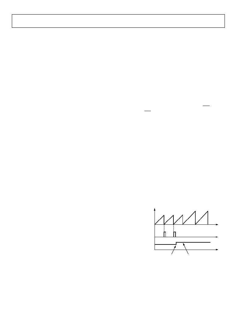
�If� a� new� value� is� written� to� the� LINECYC� register� (Address� 0x101)�
�midway� through� a� line� cycle� accumulation,� the� new� value� is� not�
�internally� loaded� until� the� end� of� a� line� cycle� period.� When� the�
�LINECYC� register� is� updated� mid-reading,� the� current� energy�
�accumulation� cycle� is� completed,� and� the� new� value� is� then�
�programmed,� ready� for� the� next� cycle.� This� prevents� any� invalid�
��E(t)� ?�
�nT�
�?� VIdt� ?�
�0�
�(14)�
�AENERGYx� REGISTER�
�0�
�E� =� VInt�
�(15)�
�CYCEND� IRQ�
�LINECYC� REGISTER�
�NEW� LINE� CYCLE�
�VALUE� PROGRAMMED�
�INTERNAL� LINE� CYCLE�
�UPDATED�
�Figure� 47.� Changing� the� LINECYC� Register�
�Rev.� B� |� Page� 26� of� 72�
�发布紧急采购,3分钟左右您将得到回复。
相关PDF资料
EVAL-ADF4002EBZ1
BOARD EVAL FOR ADF4002
EVAL-ADG788EBZ
BOARD EVALUATION FOR ADG788
EVAL-ADM1021AEB
BOARD EVAL FOR ADM1021
EVAL-ADM1023EB
BOARD EVAL FOR ADM1023
EVAL-ADM1031EB
BOARD EVAL FOR ADM1031
EVAL-ADM1062TQEBZ
BOARD EVALUATION FOR ADM1062TQ
EVAL-ADM1075CEBZ
BOARD EVAL FOR ADM1075
EVAL-ADM1087EBZ
BOARD EVALUATION FOR ADM1087
相关代理商/技术参数
EVAL-ADF4001EBZ2
制造商:Analog Devices 功能描述:Evaluation Board For Pll Frequency Synthesizer 制造商:Analog Devices 功能描述:ADF4001 PLL SYNTHESIZER EVAL BOARD
EVAL-ADF4002EB1
制造商:Analog Devices 功能描述:EVAL BOARD - Bulk
EVAL-ADF4002EBZ1
功能描述:BOARD EVAL FOR ADF4002 RoHS:是 类别:编程器,开发系统 >> 评估演示板和套件 系列:- 产品培训模块:Obsolescence Mitigation Program 标准包装:1 系列:- 主要目的:电源管理,电池充电器 嵌入式:否 已用 IC / 零件:MAX8903A 主要属性:1 芯锂离子电池 次要属性:状态 LED 已供物品:板
EVAL-ADF4007EBZ1
功能描述:BOARD EVALUATION FOR ADF4007EB1 RoHS:是 类别:编程器,开发系统 >> 评估演示板和套件 系列:- 标准包装:1 系列:PSoC® 主要目的:电源管理,热管理 嵌入式:- 已用 IC / 零件:- 主要属性:- 次要属性:- 已供物品:板,CD,电源
EVAL-ADF4106EB1
制造商:Analog Devices 功能描述:PLL, Frequency Synthesizer
EVAL-ADF4106EBZ1
功能描述:BOARD EVAL FOR ADF4106 RoHS:是 类别:编程器,开发系统 >> 评估演示板和套件 系列:- 标准包装:1 系列:PSoC® 主要目的:电源管理,热管理 嵌入式:- 已用 IC / 零件:- 主要属性:- 次要属性:- 已供物品:板,CD,电源
EVAL-ADF4108EB1
制造商:AD 制造商全称:Analog Devices 功能描述:PLL Frequency Synthesizer
EVAL-ADF4108EBZ1
制造商:Analog Devices 功能描述:Evaluation Board For ADF4108 制造商:Analog Devices 功能描述:ADF4108 Evaluation Board 制造商:Analog Devices 功能描述:ADF4108, PLL FREQUENCY SYNTHESIZER, EVAL BOARD; Silicon Manufacturer:Analog Devices; Silicon Core Number:ADF4108; Kit Application Type:Clock & Timing; Application Sub Type:PLL Frequency Synthesizer; MCU Supported Families:ADF4108 ;RoHS Compliant: Yes